
Automata
Project Goal
In this individual project, you will design and build an automata using planar mechanisms and a hand crank. Model, fabricate, and assemble an automata inspired by nature (this could be your favorite animal or plant, or a landscape). You can start by selecting a mechanical movement that inspires you, or you can envision a story you want to tell first; and eventually, both will have to blend together for a successful automata to be completed. The mechanism may stand alone or integrate with another one, but you should include at least 1 mechanism of your choice. Some of the choices are gears, cams, Scotch yokes, slider crank, irises, ratchets, geneva wheels, and linkages (among many more). Use a clock cage as your main structural component to contain your mechanisms and shafts.
Executive summary
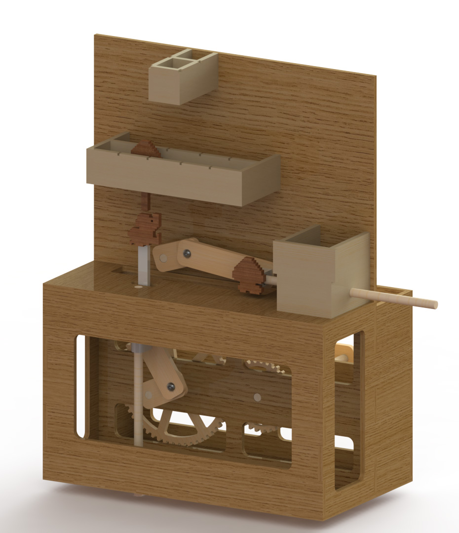
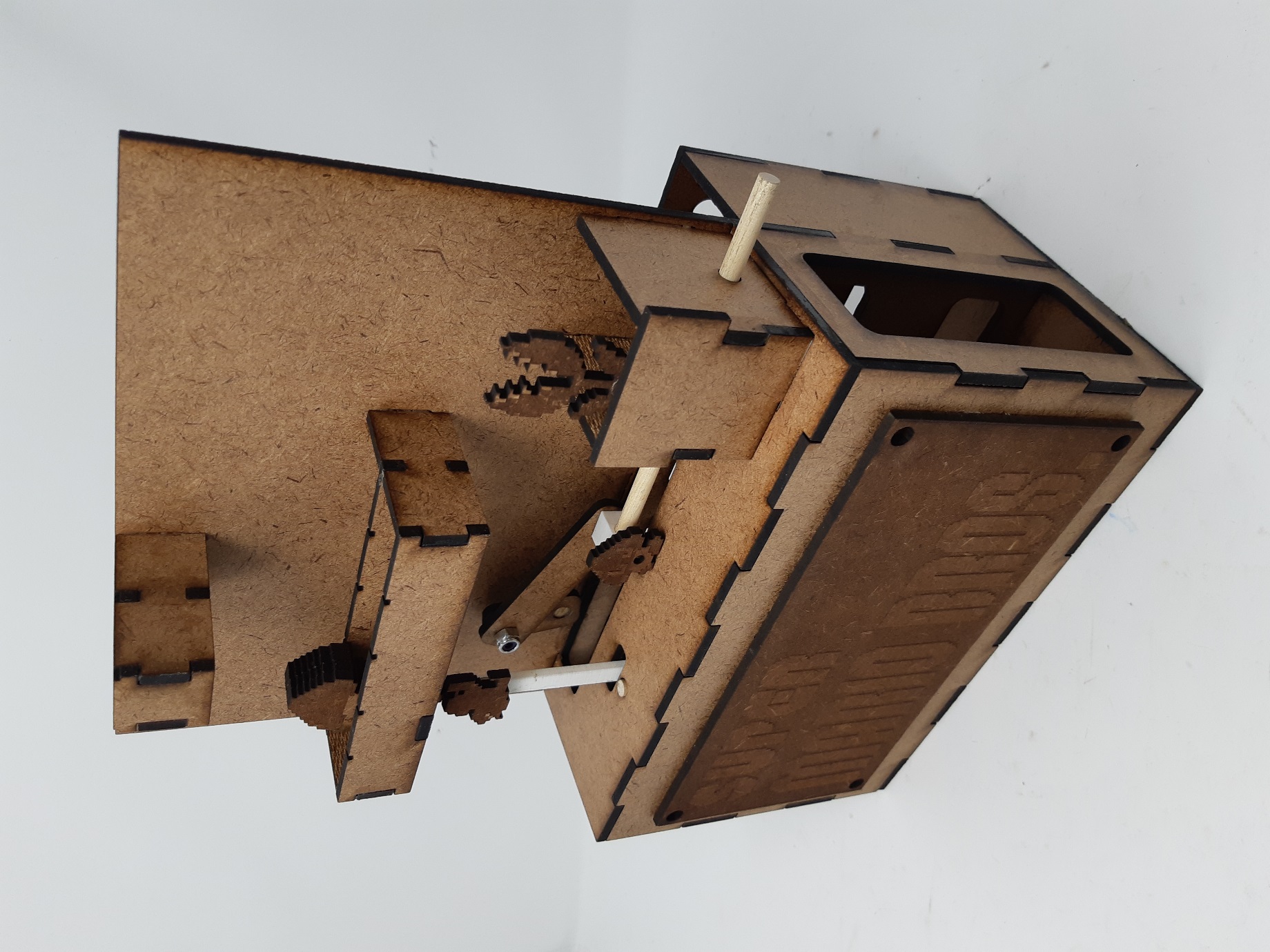
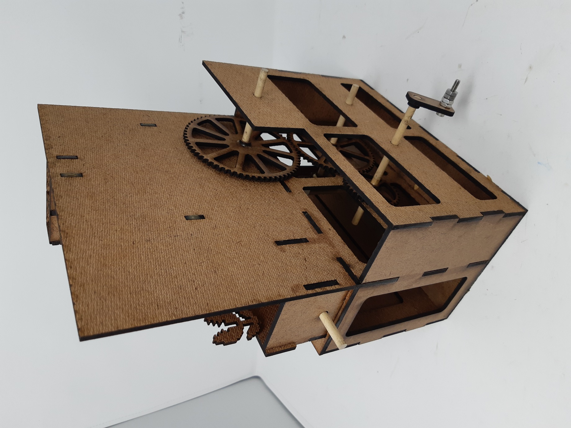
When I got this assignment, I wanted to do a project on a landscape. After some thought, I realized creating a scene about Super Mario Bros. game would be a cool choice to do as automata, partly because I am a big fan of the game and jumping motion in the game caught my eyes. I choose to create the very first scene from the original Mario game where Mario hits a block to get a mushroom since I thought that would be one of the most famous scenes in the entire game history.
My first design had a complicated mechanism. It used 6 gears, three cams, and a slider crank to create four different motions. Already too complicated just by looking at the number of mechanisms. Eventually, all the mechanisms did not work at all. I had to pivot to a simplified design that is feasible. Later, I decided to only create two different motions for my automata, which were two slider cranks.
My final design has these mechanisms:
-
4-inch gear
-
3.5-inch gear
-
2-inch gear
-
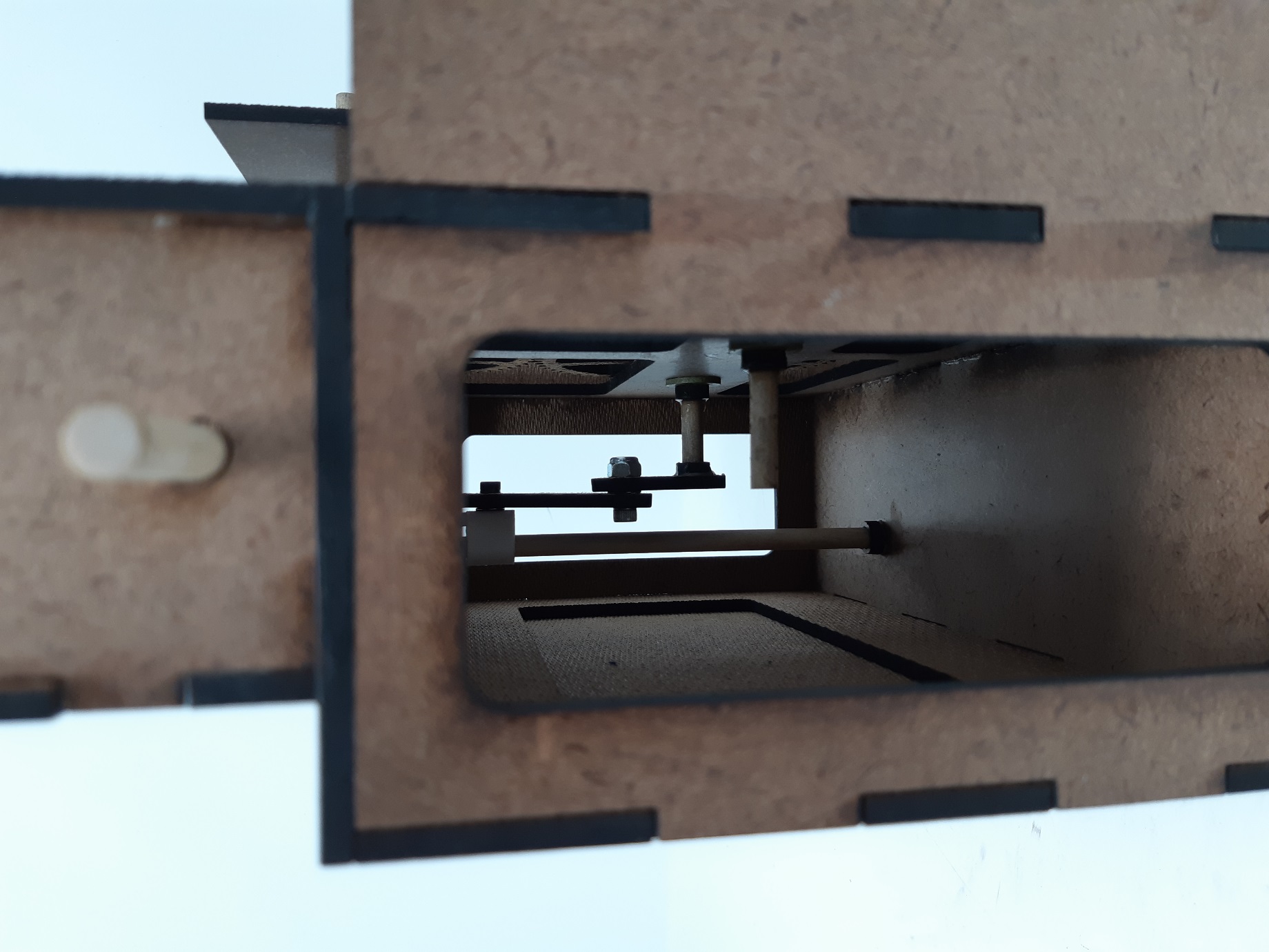
Slider crank with bar length 1-inch, 1.5-inch
-
Slider crank with bar length 1-inch, 2-inch
Using mechanisms above, I was able to create motion where small Mario jumps up and down while a mushroom monster moves horizontally right and left. Edition to that, I added a small mushroom above the Mario character so that the mushroom also moves up and down as slider crank pushes the character up and down.
I choose to use gears because they were effective in transmitting force to another component easily, especially when the material for the project is hardboard. They were easy to fit together, as far as the gear size was big enough to ignore the laser printer’s kerf. I also choose slider crank as my main mechanism because cam did not work well with the hardboard due to the friction, and slider crank was effective enough in creating 1-dimensional movements. I gave the 0.5-inch difference to the sizes of the main gears connected to each slider cranks so that two objects attached to it can be in a little different position every time I turn the gear.
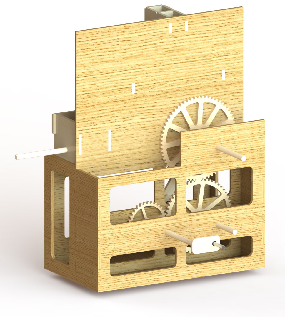
SolidWorks Model
Actual Automata
Demo
Reflection
It was a hard journey. It took me a whole week to build the initial design, and by the end of the week, I realized something was wrong with my model. I asked for an extension and was able to spend half a week more to finish it. I learned a lot of things while doing this project. I don’t feel bad at all about the extra time I spent on this project, due to several lessons I learned.
First thing I learned, is that it is sometimes necessary to keep structures simple, especially when you don’t really know well about what will going to happen in real life. I was so excited about this idea of Super Mario automata that I did not realize that it will take so much time CADing my initial sketch and that it will take more time to actually build it. As a result, by the time I finished my CADing, the long three-day weekend already ended. It took forever to laser print the materials on the weekdays, and it took me hours and hours until the wood glue dried so that I can start connecting other parts. I was completely messed up with my time management, clearly spending more time than I’m supposed to spend. I should have thought wisely, thinking more about the feasibility of the model not only by the physical factors but also by the time factors.
The second thing I learned was that there are times when you must admit you are wrong. While I was doing my assembly, I had a little feeling that my design might not actually work since my cam designs were too abrupt, meaning I clearly thought that there might be issues with them. However, I was reluctant to admit the fact and rather convinced myself by saying everything works fine on the SolidWorks. However, by the time I started my assembly in the real world, I learned the hard lesson – “Not everything on SolidWorks works in real life”. Using the same materials for contact on the cam structure was a very unwise choice to do, not being able to finish making the first design because they did not work at all.
The last thing I learned was that it is always wise to put dimensions you are unsure as variables in SolidWorks. I had several experiences where the thickness of the cut sheet was different from what they are told to be. For example, even though I used 3/16” board this time, all of them had a thickness less than 0.16-inch which is much thinner than it is supposed to be. By setting my thickness as a variable, I was able to save a ton of time I might have spent modifying my CAD files, by just changing the single value.
Overall, I loved the project. I was so thrilled to see my mechanisms working smoothly at the final moment. I learned a lot about linkages and cams, and about how to use SolidWorks to create mechanical mates. I feel more comfortable using SolidWorks, and I feel like I’m ready for some big project!