Clockstrolabeoscope
ENGR 2330: Introduction to Mechanical Prototyping, S/P Sculpture Project
Executive Summary
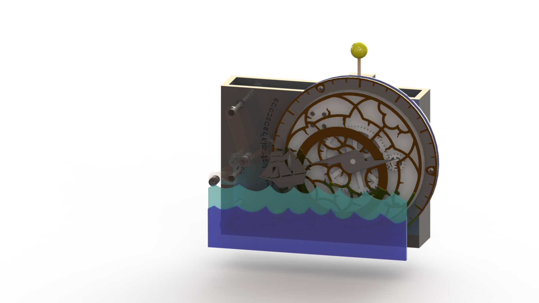
Our team was inspired by the astrolabe, ancient navigation tool used to plot location according to the stars. We implemented the designs from 16th-century renaissance astrolabes and created our sculpture putting some extra feature to the structure like lens and ship to add more renaissance taste. Although the structure may not be used for actual navigation purpose, it achieved a certain amount of aesthetic values created with 5 distinctively different mechanisms
-
3-layer astrolabe, with each layer turning a different direction
-
Renaissance styled ship moving back and forward with a slot-slider
-
Four-bar linkage with a lens attached, that floats around offset to the astrolabe
-
Sun moving up and down using a cam structure
-
Chain structure transmitting power from the main shaft (astrolabe) to other mechanisms.
I dedicated myself to creating the 3-layer astrolabe, which used 7 gears of different ratio to create an opposing movement for each layer. Speed of each layer wasn’t calculated since it wasn’t the important point for this structure. I also assembled everything together by creating a box that can hold everything together. If I had more time, I wanted to change the shape of the box from a simple rectangle to a more appealing shape, but sadly it did not happen due to lack of time.
There were a lot of difficulties to this design, especially focused on the astrolabe and the gears attached to it. Using a 10-inch sized planetary gear was a big challenge, and only relying on three rollers to support the outer ring connected to the planetary gear was more challenging. Since a total of 7 gears were used, precision was a very important factor since a little difference in angle or dimension had the danger of making the whole structure stop working. It actually happened several times during the assembly process, which added extra hours of work to fix. Eventually, all the mechanisms worked fine as we intended, except for the cam which we had to limit the movement to avoid the high friction it was causing to the main shaft.
Detailed design
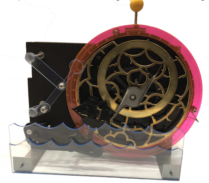
The actual design had several changes from the render. First, the outer layer of the astrolabe was replaced with a laser-printed acrylic instead of sheet metals, due to difficulties in cutting thin sheet metals with a plasma cutter. Second, several sheet metal brackets were added to hold the box structure together. Also, a lot of 3D-printed hubs were added to prevent movement of the shafts, which we did not consider in the CAD. Lastly, the movement of the sun had to be restricted, due to the high friction it was creating.
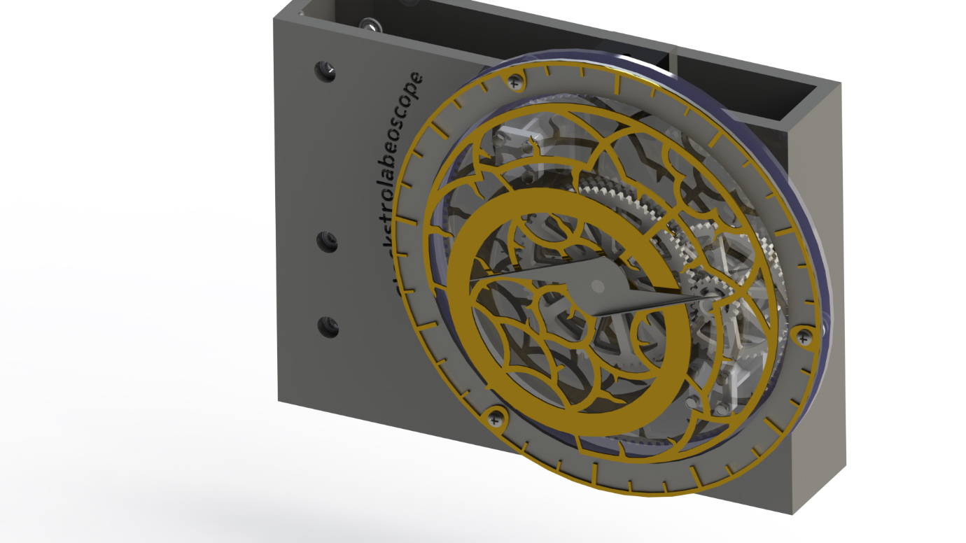
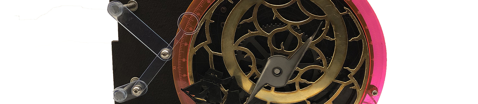
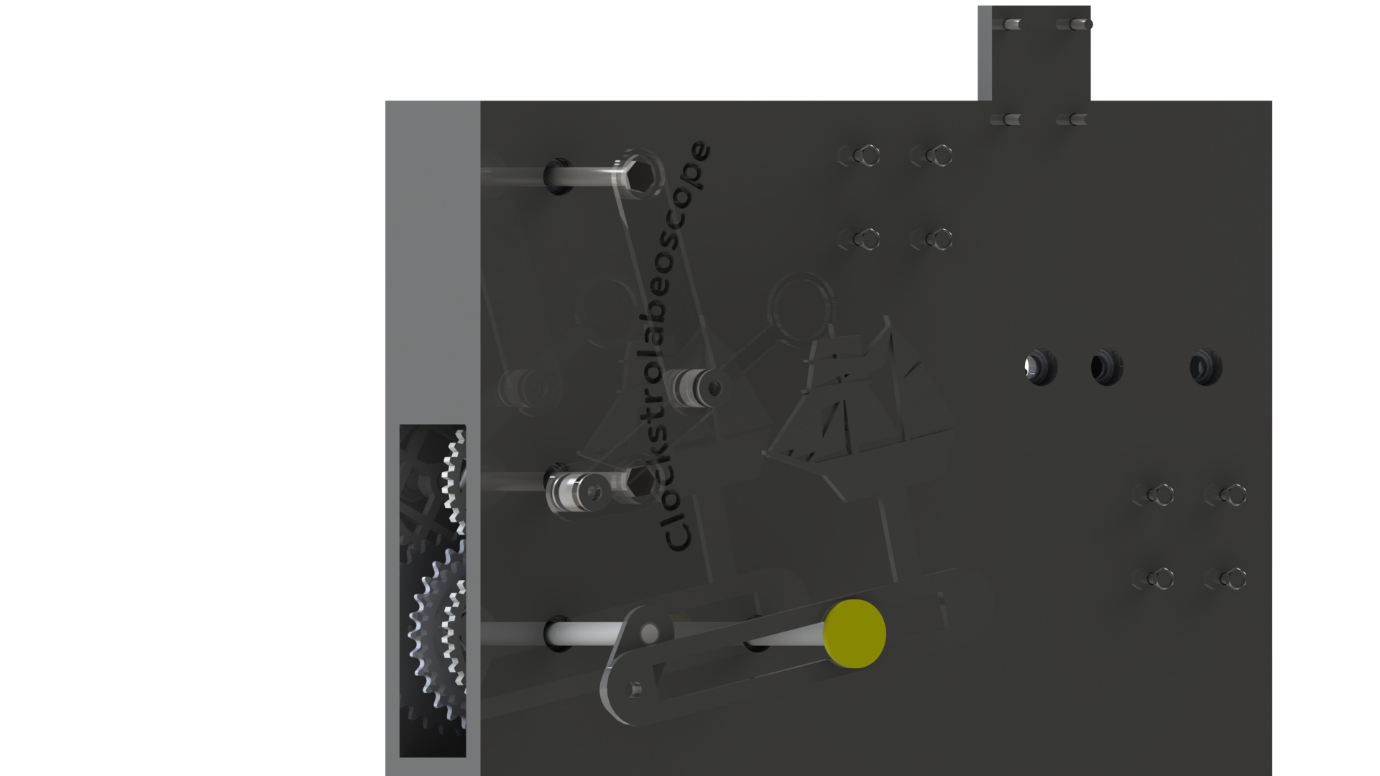
The astrolabe structure was my main contribution to this project. It was designed by me and fabricated by me, Becca, and Eric. The main design goal at the beginning was to create a structure that has 3-layers that each turn in opposing directions. For example, if the outer ring was turning clockwise, the layer inside should turn counter-clockwise, while the needle in the middle should turn clockwise. It seemed like an easy task at first, but it became complicated since all three layers had to turn different directions.
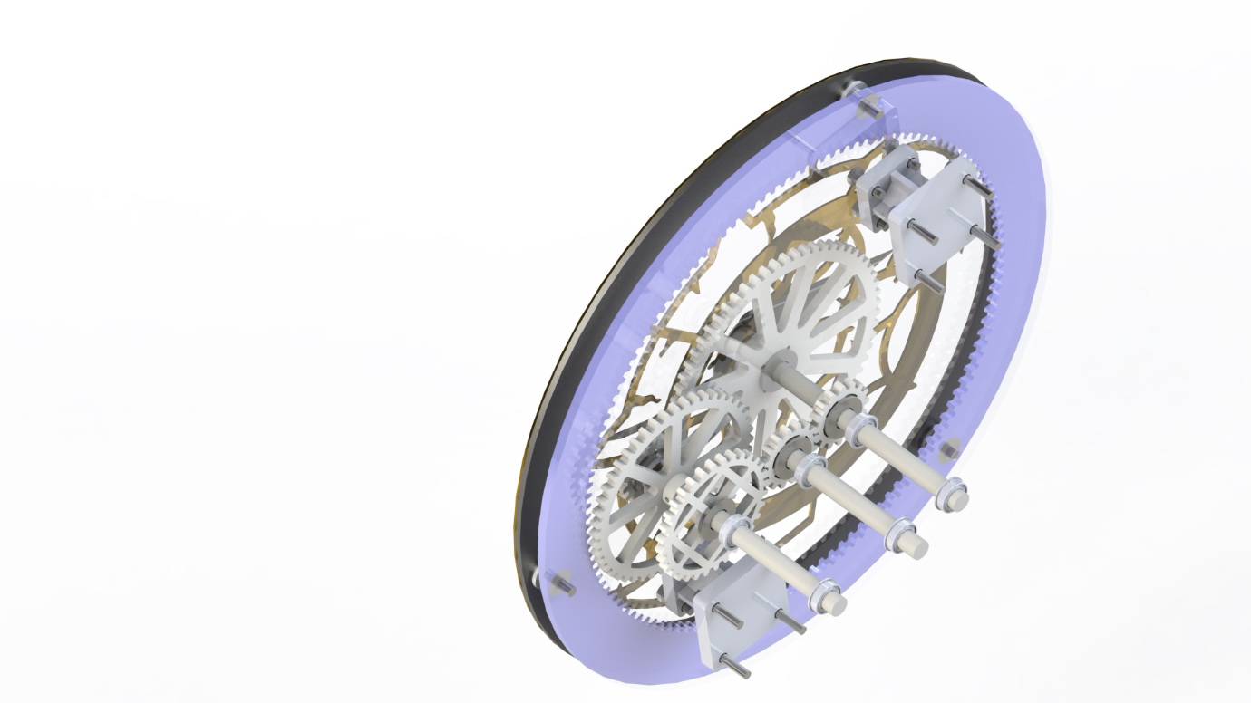
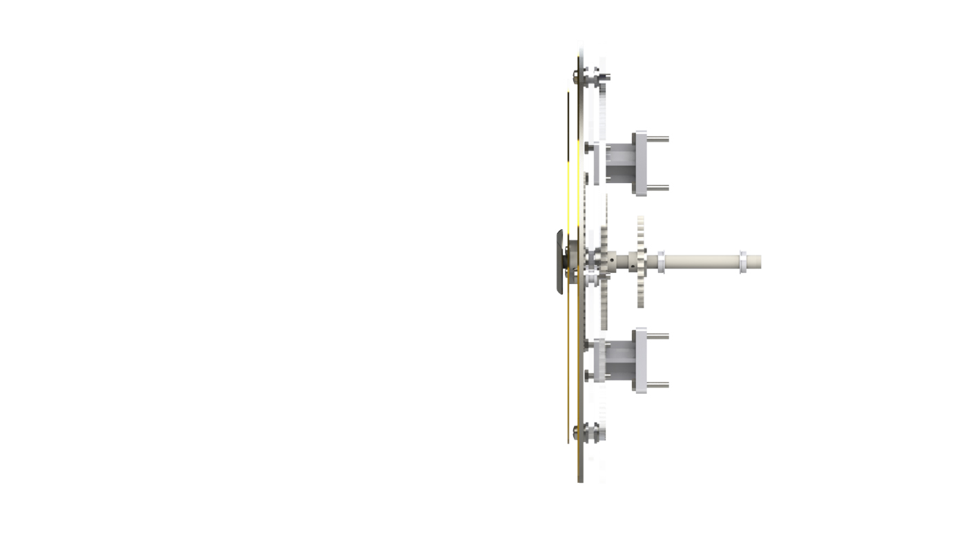
I got the idea for putting extra gears looking at the structure of clocks, which also have 3 layers turning at a different speed. I decided to use three shafts for the whole structure, where the Main Shaft transmit the power from the motor directly and turns a small gear at the back and the needle attached in front. The Extra Shaft is used only to change the direction of rotation of the gears connected to the Transmission Shaft, where it transmits power to the planetary gear and gear in front to move two different layers. The way the second layer (the layer with fancy brass decoration) move is very interesting since it is attached to the Main Shaft with a bearing. So, it gets the support from the Main Shaft but is not dependent on its rotation. The second layer only gets the power from the gears from Transmission Shaft, from the small gear that rotates the 4-inch sized gear in the middle.
The outer layer is dependent on the planetary gear powered by the gears in the Transmission Shaft. However, since the planetary gear lacks the support to hold it in place, three 3D printed rollers are attached – they roll on the supporting disc in between the layers. This made the whole structure much more fragile and unstable, but I couldn’t think of a better way to create the same mechanism.
Thanks to Becca and Eric, the brass decoration and aluminum needle were fabricated with great detail. I was concerned whether the brass decoration will print well on the plasma cutter, but fortunately, it printed perfectly just with little warp. I had to reprint the planetary gear and rollers several times due to high friction caused by gravity, which wasn’t a factor when I was designing it in SolidWorks. Hopefully, acrylic gear worked fine due to the extra space created by kerf of the laser printer.
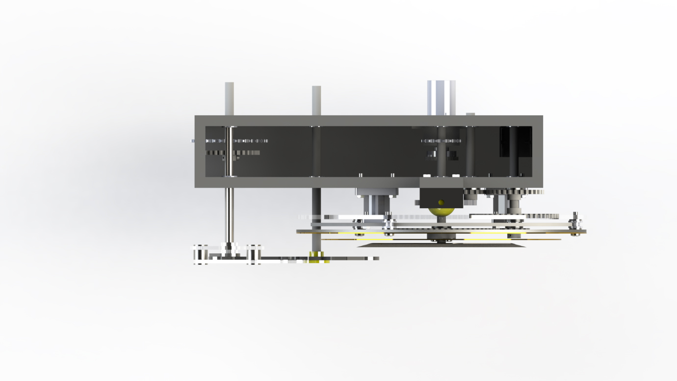
The structure inside the box was simple, having the Main Shaft getting power from the motor under it (green highlighted part) through gears, and transmitting the power to the other shaft using sprockets and chain structure (blue highlighted part). We did not have a tensioner for the chain, but luckily, the 3D printed motor mount acted like a tensioner, making the chain to work perfectly.
Four bar linkage and the slot-slider are powered by the sprocket connected to the chain structure. Even though two structures are in the same offset from the box, they do not interfere because the shafts powering them are rotating with the same speed in different directions.
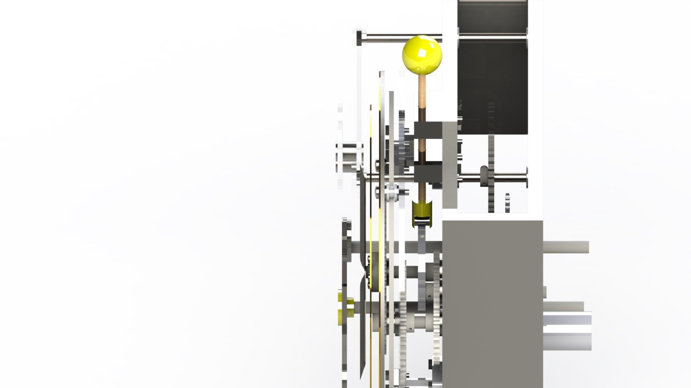
The cam structure is powered by the cam connected to the Main Shaft. However, since the main shaft experiences the highest RPM among the structure, friction quickly became a big issue when actual assembly happened. To prevent all other structure stop working due to the friction, we set a limitation for the cam movement so that it just goes up and down about 0.3 inches, instead of full 1 inch. It was a sad movement, but it was necessary to save the whole structure.
Reflection
The design process was a bit challenging and stressful for me. During the ideation process, we decided to create a 3-layer disc structure, but no one really knew how to create it. I took the charge of designing the whole structure, not knowing how long it will take for me. I think all my team members did not realize that too since we thought it would be a simple task while we were talking together about it. However, as soon as I started designing it, I realized the issue isn’t simple as expected. A two-layer structure is simple, but when it comes to a three-layer structure, interference between shafts and gears became such a critical issue.
I had to go through many sketches, testing, and feedbacks until I reached the final design I already explained in the detailed design section. I realized that I spent a total of 35 hours designing the astrolabe, plus an extra 12 hours finishing the assembly for the team. I spent much more time on the CAD process compared to other teammates, first because the structure itself required much more CADing, but second because ideation and testing process took much more time than I expected. I don’t regret my choice since I was excited to dedicate myself to a very essential portion of the project, and at the end, it came out great.
During the project, I definitely learned the process of designing and fabricating, learning new tools like ShopBot and plasma cutter. I learned a lot about the gap between ideal situation happening inside the simulation world and the real world and methods to deal with them, such as the warp happening to our brass structure after plasma cutting. Since I had to spend a lot of time on CADing, I’m more used to using the tool than I was before, ready for a higher level of designs for future projects.
Extra thing I learned from this project is how to work with other people in a mechanical project, both in good ways and bad ways. The positive side was that I learned the positive side of working together with other people, where a team project can achieve much a higher quality of work compared to a single person. People discuss the idea together, creating a higher level of design for a structure. Also, people work together, creating work in a short period of time. There is no way that I can work more than 300 hours to finish a project in a time span of 4 weeks, which is about the person-hours the project took to finish.
However, the negative side of team project was the thought of “Someone will be going to do the work instead of me”. Even if there are some works to be done, I had the feeling that people wanted to get away from the tasks because it consumes their time and energy, as well as the responsibility of taking charge of the task. It happened several times in our team, where no one tried to finish the assembly process until the last minute. Actually, I was also reluctant at doing it since I thought I spent enough time already to the project. However, I realized that no one will recognize how hard I worked on the project, and people will generally not care about it unless you express them face to face with them. I did not realize this until the last moment, getting stressed by myself, volunteering for more works that should have been done a long time ago.
I think my team lacked communication in general, which happens a lot to a team project. Half the conversation done in the group chat is done after April, which was the last moment. I feel like my team could have done much more smooth teaming process if we communicated more, work together little more, and discussed work more face to face.
Conclusion
The structure worked very well, better than I expected. The designing process was a little stress for me, but the fabrication and assembly process were a really fun time. Even though we had to assemble everything for 12 hours until 4 am in the morning, looking at our mechanism finally working in the real world was enough reward for it. It might’ve been sad if the structure did not work at all at the end, because we overall spent so much time on this single project.
There are some requirements that we had to skip at the last moment, such as metal folding parts we had to get rid of because it was not fitting well at the last moment. Also, we realized that the thickness of the whole structure was little more than 6-inches with the wave attached due to the motor sticking out, but it was too late to fix the structure. Other than that, it was a very satisfying project where I had to use my knowledge learned from the Mech Proto class to finish. I definitely achieved all the objectives I set for this semester, maybe little more than I expected from the class.