
The Dragon Tales
ENGR 2330: Introduction to Mechanical Prototyping, TS Sculpture Project
Executive Summary
Our team decided to create the sculpture about the traditional medieval myth – the knight and the dragon. As soon as we gathered around for the first time, we were talking about creating a big structure of a dragon or a phoenix. Since some of our teammates wanted to create a cool knight structure along with the sculpture, we decided to set our theme as the knight and the dragon. As a result, our structure was made to have:
-
An 8 to 9-inch-tall red dragon structure made with 16 different bone layers.
-
Fire cam structure that pushes fire up and down.
-
Slot slider that moves the knight back and forth.
-
Stationary cam structure that changed the angle of the sword connected to the knight.
-
Four gears that transmit power along with the whole structure.
-
Two giant wings made of two separate four-bar linkage mechanism.
-
Chain drive that transmits power from the gears to the sprocket that connects the wing structure.
-
Milled and lathed parts, like shafts and motor mount
I dedicated myself to creating the dragon and the wing mechanism. The dragon design was originally from a video game called ‘Monster Hunter’, which I got the 3D mesh modeling and modified the pose using the program ‘Blender’. Inspired by the metal fish structure displayed on Olin Academic Center, I decided to create a design that resembles an undead bone dragon. This choice was made also because we were originally thinking of plasma cutting the dragon structure out of metal, so I created flat bone structures so that we can plasma cut them easily. Though, this part was later created by 3D printing due to a lot of difficulties in connecting the plasma cut metal pieces.
The wing mechanism was inspired by the “Da Vinci Machine” structure created by one of the team during the last project for mech-proto. However, the whole design itself was created and measured by me, going through a lot of testing trying to make the best ratio which the structure works. Overall, my team did not suffer from mechanism issues for this project. There were some issues when we were fabricating and assembling the structure, but the overall design was built so that it works well in the CAD model and is supposed to work well in the real world without a lot of concern.
Detailed design
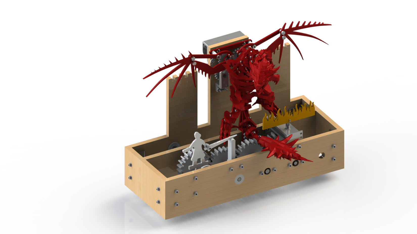
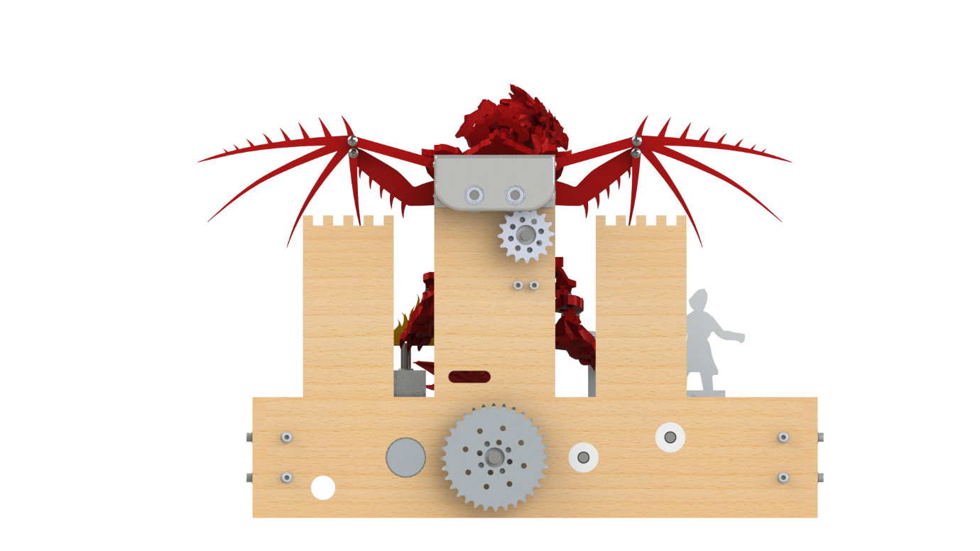
The actual design had almost everything the same as the render except for one part – the fire cam structure. First, we added extra fire design in front of the fire cam structure to add more aesthetics to the structure. However, there was an issue of hex shaft not lining up after being connected to the motor, eventually making the whole structure to stop. So, we decided to remove the shaft under the cam structure, which stopped cam from functioning but saved all other mechanisms.
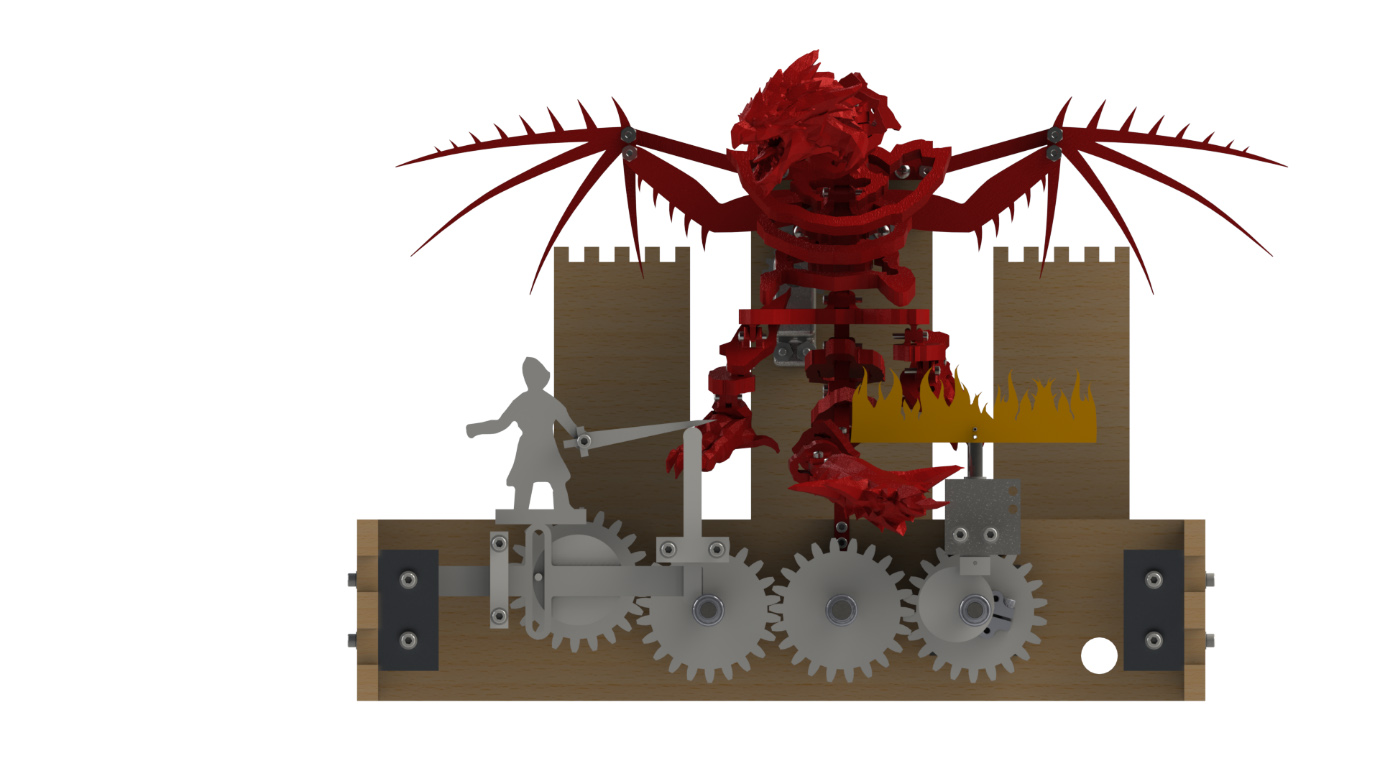
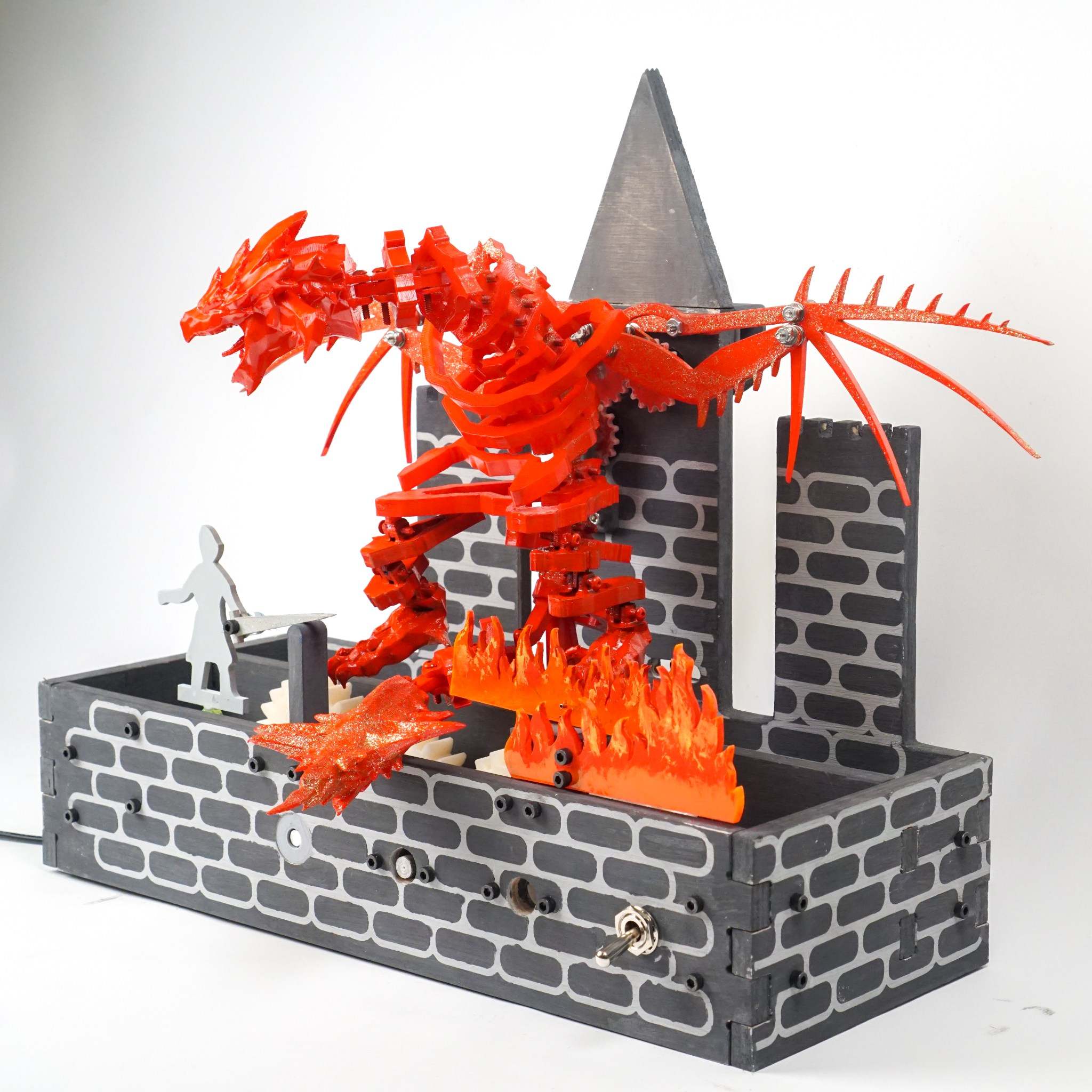
The front view of the rendering model shows all the mechanisms well. The far-right gear is connected to the motor, turning about 28 times per minute. The far-right gear is also supporting the cam that moves the fire structure up and down. The middle gear that is attached next to the far-right gear is the sprocket gear, where it turns the sprocket attached at the backside of the structure and transmit power to the wing mechanism. Gear at the far-left is the slot-slider gear, which creates back and forth movement as it turns.
The backside of the structure has two sprockets sticking out, which is connected by a chain mechanism in the real structure. Using a half-link, my team was able to tension the chain without using an extra tensioner. The backplate is designed to look like a castle to add the detail to the story of the structure. As you can check from the picture from the real structure, all the structure is painted with gray color and white brick patterns to look like a castle. Also, the extra 3D-printed structure is attached at the top of the castle to support the gears that power the four-bar linkage structures.
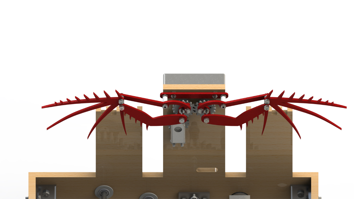
Finally, the wing structure is powered by a gear that is connected to one of the sprockets at the backplate. Wing structures are basically duplicate of the same structure, just functioning in a different direction. Straight lengths from each hole are strictly calculated to avoid any collision issues. All the pieces are connected by fasteners, which was a little concern before the wing structure was built. However, since the wing wasn’t experiencing very fast movement, just using the fastener was enough to hold the structure rigidly in place.
Reflection
The design process was an entertaining experience for me. During the ideation process, I knew what I wanted to do as soon as the topic was chosen, and I was able to persuade teammates with the sketch I brought during one meeting. It was a sketch that showed how possibly we can fit a whole dragon inside the 6-inch thickness limit, by curling the dragon in a vertical position. I also came up with the idea of making a dragon with bones layered like a metal fish structure displayed on Olin Academic Center. People were convinced with the idea, and I was eager to work on it even though I had no clue how to. I was just excited about the fact that I can design a cool dragon for my final project in mech-proto.
The designing process was a bit challenging. I realized that using a license-free dragon design from the web will be much easier for me to create the bone structures for my dragon design, as well as being more appealing to people since I lack the skill to draw and design stuff. I got 3D mesh dragon model from a game but realized they are not in the curling position as I wanted. To figure out how to change the shape of the 3D mesh model, I had to look for Google for several hours and realized that a program called “blender” is easy to manage. Again, I had to learn the program for several hours before I was finally able to create a 3D model dragon with the appropriate pose. Creating bone structure from the original design wasn’t challenging compared to the last process, but it still took a lot of time, and the process was especially tiring since it was redundant work done for 16 times. However, I was so satisfied with the design I created that I forgot about the time I had to spend on creating the dragon design.
The wing part was supposed to be another teammate’s work. However, since Jack said he couldn’t really CAD, I had to take over the job and create the mechanism so that he can put the designs on it. I thought it might not be a long process, thinking that I already have an example from the last project’s work, the “Da Vinci Machine”. However, I realized that the wing structure we wanted to create had little different design than the machine, so I had to create it from nothing. I had to go through a lot of testing inside the SolidWorks program to make sure that everything worked. What I realized was that some parts stop working even if I just change the dimension by 0.01 inch, which was amazing to see. I’m not even sure how I managed to find the correct dimension for everything, but I did it somehow at the end.
From this project, I learned how good teamwork is supposed to be done. We organized everything on time, set due dates for next works, frequently met to just check what is happening to each other’s work, and often gave or took works from each other in case that person couldn’t work on it. We felt like we were always ahead of other groups and was not forced to rush before each design reviews since they were ready a long time ago. We even managed to finish the whole project two days before the due date, which is amazing thinking that my last project ended at 5 am on the morning of the presentation day.
I think this was achieved by my team keeping all the structures simple as possible, avoiding any structure that might have a concern. It’s not a good stance as an engineer to avoid all the challenges, but thinking that we had such a limited time, I think this choice really saved our time and health.
Conclusion
The structure worked very well, better than I expected. Everything went too well for this project that I’m worried about possibly having worse teamwork next year. Maybe, I can implement the experience from this teamwork so that I can lead the team to have healthy teamwork, even though I know that I’m not usually a person who leads a team. I did not learn many new skills from this project since I used most knowledge from what I learned already, but it was a really good experience to create the design we created inside SolidWorks in the real world.
It was a very satisfying project to end the mech-proto class, which taught me the basics of CAD. Thinking that I was a person who did not even know what a CAD is about a year ago, this is very impressive progress I made just in half a year. I don’t really know whether I will keep myself working in the mechanical engineering field, but the knowledge I gained from doing these projects will help me through my life as an engineer.