Taiko Runner
Introduction
Our goal for this lab was to create a line follower robot that follows a path on the floor. It also has to have a computer input that changes some control of the vehicle without having to reupload an arduino code.
Materials
-
Arduino
-
USB cable
-
1X 12V power supply
-
1X male barrel jack to screw terminal connector
-
4X genderless crimpterminals (for crimping to wires and inserting in the Molex connector)
-
3D printer + PLA
-
Some 24AWG stranded, silicone-insulated wire
-
1X gearmotor and wheel (provided in week 1)
-
Some solder
-
Some heat shrink tubing
Calibration
For our IR sensors, we tested out if they were working initially by attaching the sensors to a breadboard and experimenting with presenting a white paper and a black colored paper. Then we faced the sensors towards the floor and the electrical tape path. The IR reflective sensors gave out different values in arduino but in actuality their difference in voltage was only by 0.012 Volts.
Through the readings, when the sensor located on the left of our line follower was over black tape, it’s value rose to 34-35. When it was over the ground, it ranges from 30-32. When the sensor located on the right side of the line follower was over black tape, it had a reading of 31-32 and readings over the ground ranged from 28-29. We think these jumps could be from the details on the tiles, and also reflections from the ceiling lights. These jumps however did not affect the function of our follower as the readings remained consistent, and the value over the tape and over the ground are far enough that jumps in values won’t intersect into each other’s code.
Design Choices
One design choice made was the resistor value for the receiving sensor of the IR reflective sensor. We calculated that the minimum resistor value had to be around 250 Ohms. We however chose to use a 100 KiloOhm resistor as it made the IR reflective sensor more stable as lower resistances caused varying values when the sensors read the tiles and tape.
For the Line Follower, we decided not to have the face of the robot attached while it is performing tasks as it adds a lot of extra weight and the performance of the motors becomes more delayed.
Code
Since we had to control the robot without uploading new code, we decided to use Serial.available() and Serial.read() to control the robot. By using Serial.read(), we were able to get byte data of the key we typed inside the serial monitor. We realized that we receive 49 bytes when we type ‘1’, and 50 bytes when we type ‘2’. Using this fact we made so that when ‘1’ is typed, the robot starts the track. When ‘2’ is typed, the robot stops moving.
One other choice we had to make was using millis() to send the collected data to python. We decided to collect data every 100 milliseconds so that we don’t receive too much data after running.
The sensors have a threshold value of 30 and 34 for when the right sensor and left sensor are over the black tape respectively. Any value lower indicates that it is above the tile.
The program has 4 situations that it checks for:
-
When both sensors don’t detect black tape: Both motors are set to the same speed
-
When the right sensor is over the black tape: Left motor speeds up, the right motor stops.
-
When the left sensor is over the black tape: Right motor speeds up, left motor stops.
-
When both sensors detects black tape: Both motor stops, indicating that it reached the end line.
Setup
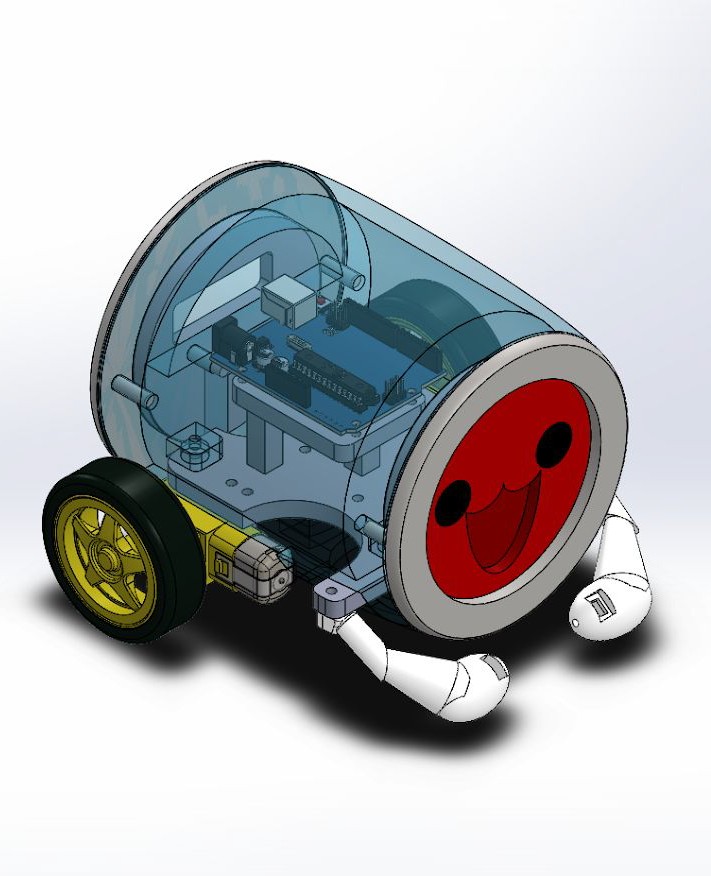
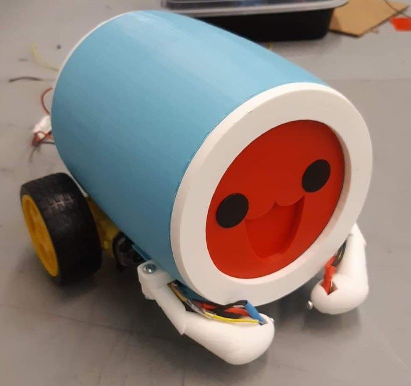
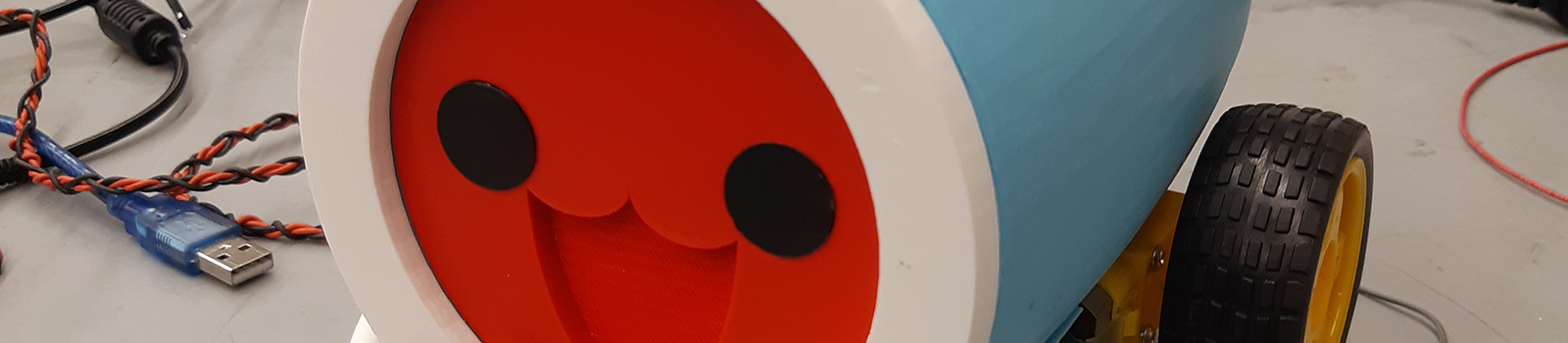
The chassis for the Line Follower we implemented the design of a game character from the game “Taiko no Tatsujin”. The CAD model was created totally by our team except for the motor and wheels attached. All the parts were 3D printed and dimensioned to fit using screws and nuts. Arduino and Motor Shield were installed inside the chassis to hide the wiring.
Each DC motors were connected to M1 and M3 slot of the motor shield for better wiring, and other wires are soldered all together so that we don’t have to use a breadboard. Using breadboard was possible since a small board was able to fit inside the chassis, but we decided not to since using breadboard had the danger of disconnected wire while we are testing our device.
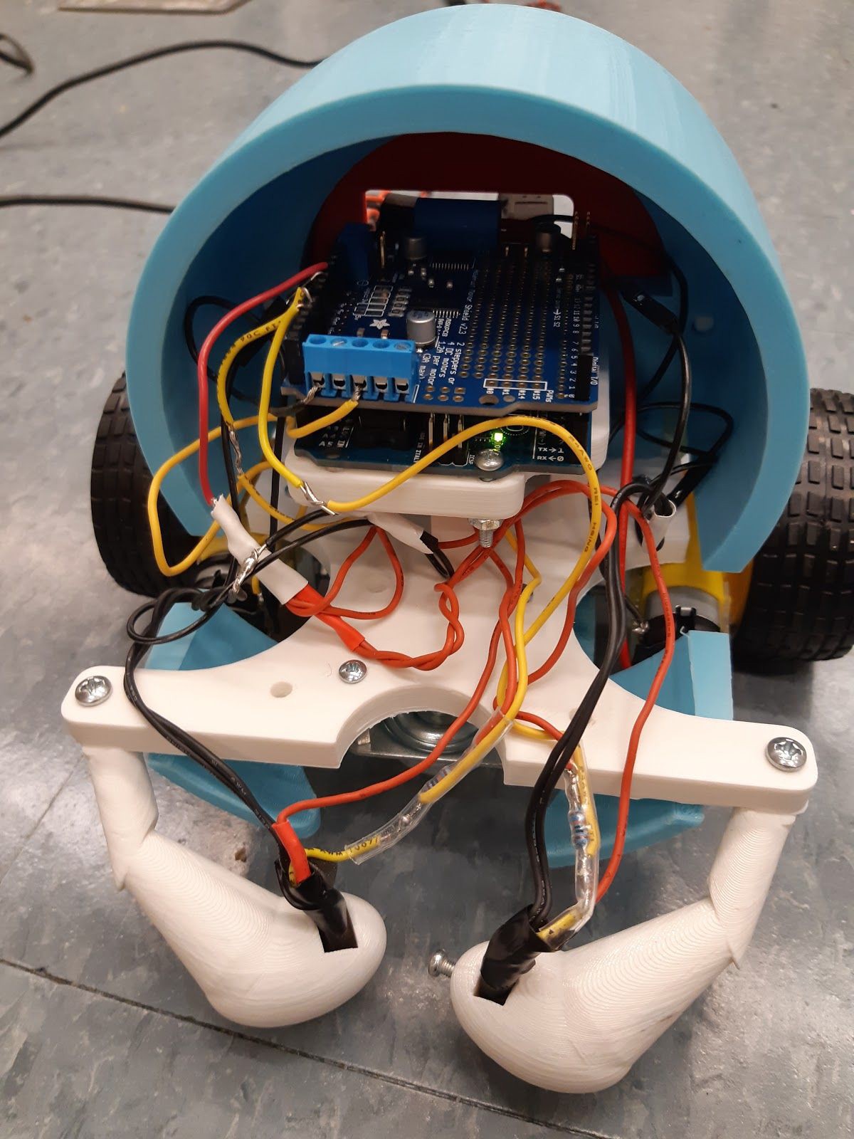
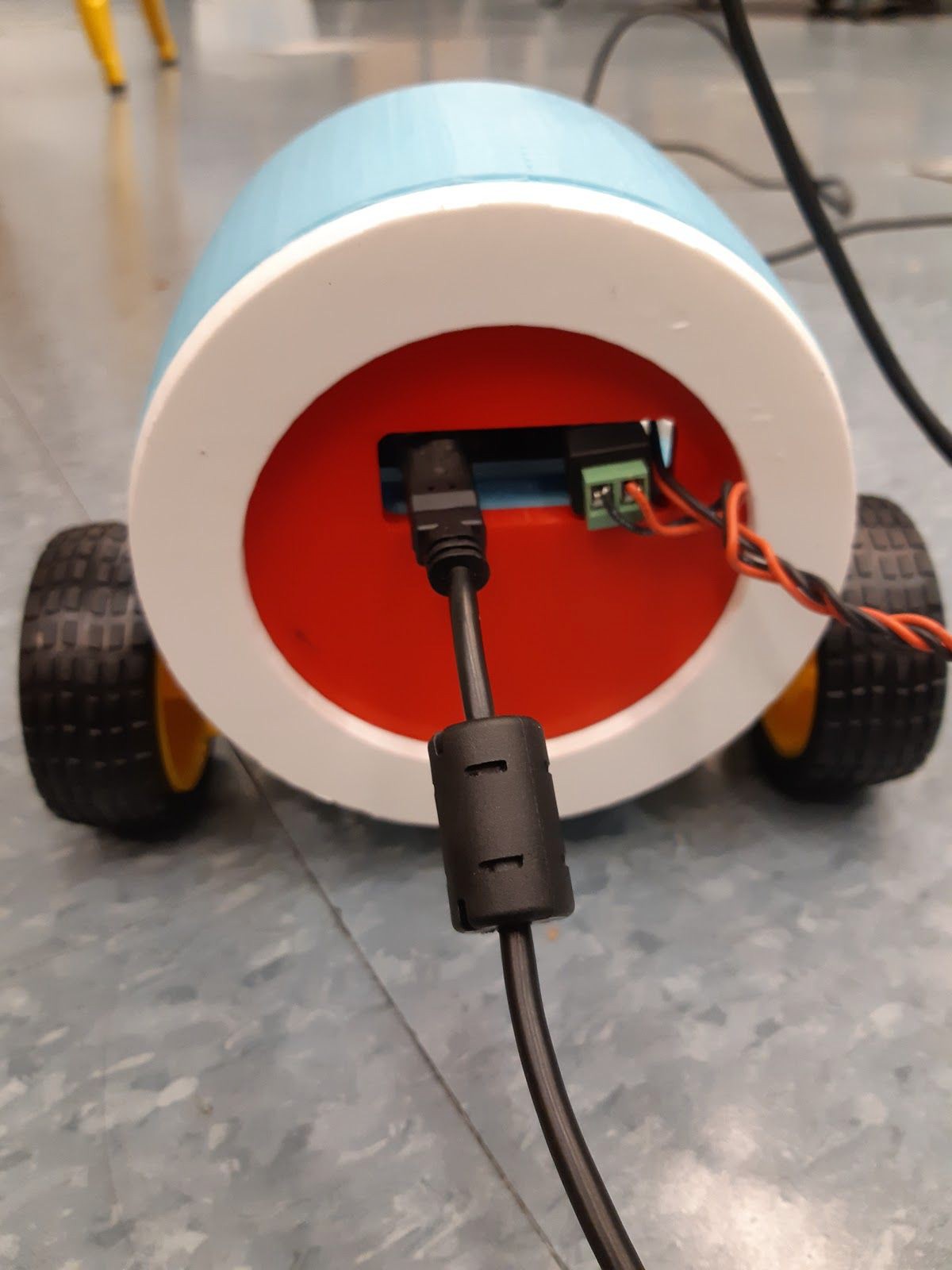
A hole was left out at the backside so that we can always connect and disconnect the power source and USB cable to Arduino. Inside the chassis, we created an Arduino mount so that the board can be fixed in place without any other temporary attaching tools.
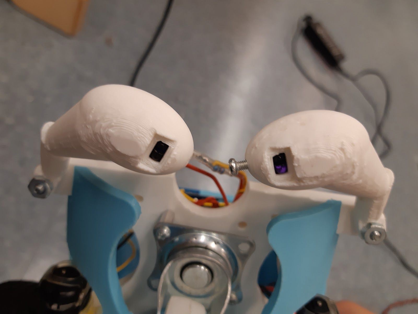
Sensors were installed inside the arm so that it can be less affected by the light around. The arms had screw holes so that sensors are fixed in place once they are set up.
Circuit Diagram
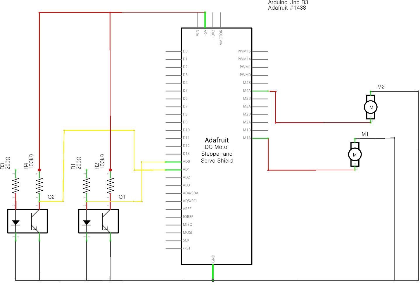
The figure above shows the schematic of our circuit layout.
Sample Test
The figure above shows the correlation between Motor Speed and the value of the IR sensor output. It is visible that whenever the left sensor reached a higher voltage (over tape) the left motor went low and the right motor went high. The same goes respectively for when the right sensor reaches its threshold value indicating black tape.
Result of Design
Using the method of having the motors have a constant speed of 30, and raise to 65 for turns were the best chosen speeds for the line follower. It was not too fast and matched well with the weight of the follower as when higher speeds were chosen it moved and jerked too frantically, and when slower speeds were chosen, the follower was too slow to make the turn.
Reflection
This project was a nice experience to practice soldering. It was great seeing our initial breadboard become compacted into just wires. Though, the breadboard itself likely would have been neater. It was also good
practicing more python/arduino interactive code. If we could improve this program, we would probably attempt to make the program more compact and add time to the if statements. Such as if an event happens for a certain span of amount of time, then make something else happen.
Another improvement we’d like to make is making the chassis more lightweight so that it can fully be attached to the device while it is running. Another improvement we would like to make is make the wiring more clean. We ran into some problems with the sensors as the wires hang out of the chassis a bit. Next time, we’d like to measure the wires before soldering and use more heat shrink.